Midi Theremin
Nearly 100 years after it was invented, the theremin remains one of the most alluring and mysterious electronic instruments. Theremin’s traditionally use two conductive sensors to measure the distance between a user’s hands and the instrument, allowing a musician to control pitch and volume by waving their hands through the air.
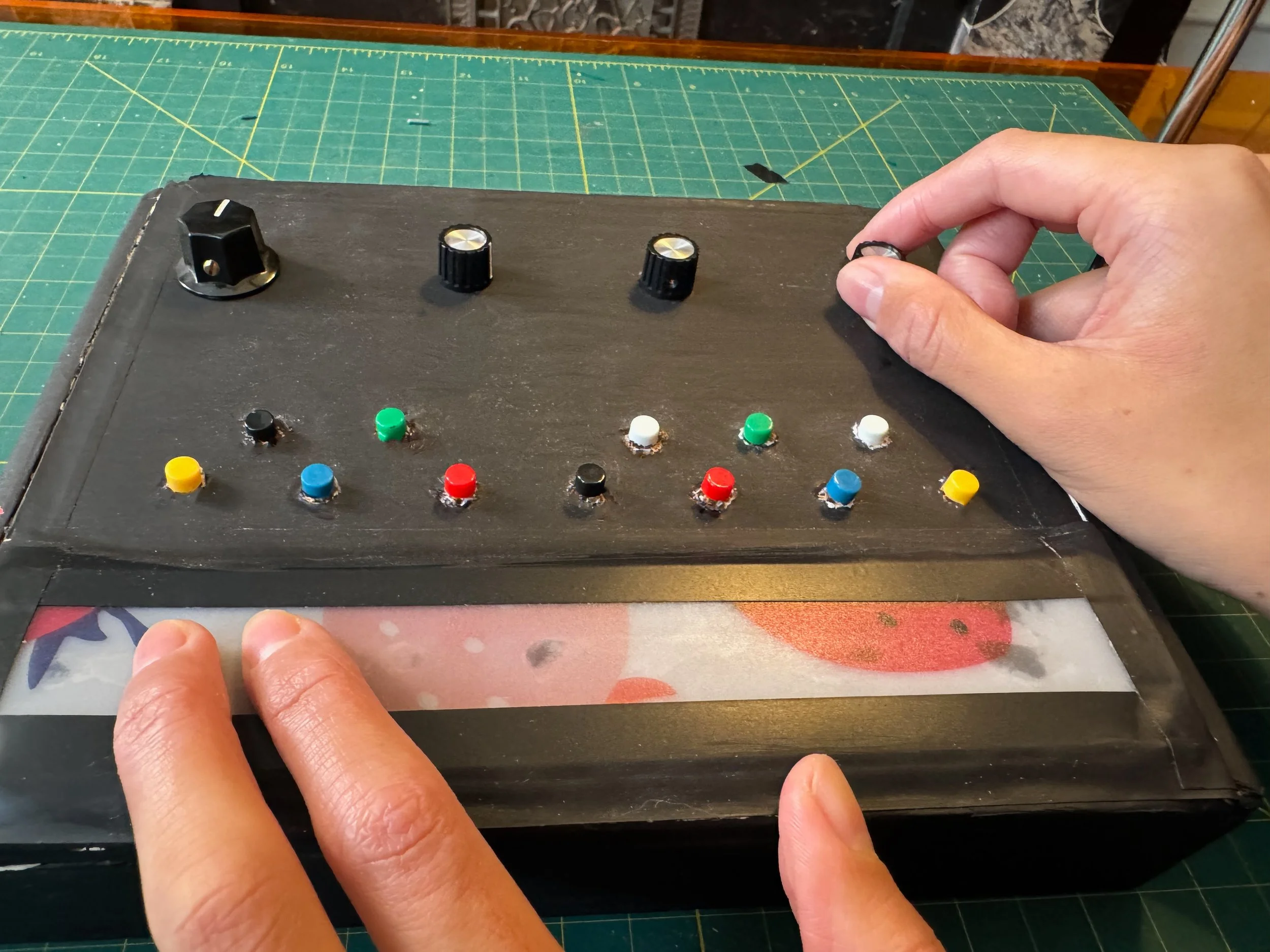
My adaptation of the theremin keeps one conductive sensor, while adding a score of other tools to manipulate sound in new ways. A touch sensitive ribbon controller stretches across the width of the box, while a 12 tone keyboard and four rotary potentiometers give flexible control over the instrument. In this way, a user can wave their right arm around the antenna sensor to control one parameter, while using the more tangible on board controllers to finely control more parameters.
As the name suggests, the Midi Theremin outputs midi, allowing you to map any control to any musical parameter. For example, you may map the 12 buttons to represent the 12 tones of a a keyboard, the ribbon controller to a filter cutoff, and the capacitive antenna to volume. Using different actions you can control nearly any parameter of a musical composition!
The project is built with a Raspberry Pi Pico, a cigar box, velostat conductive tape, basic electronic components, and scrap plastic.
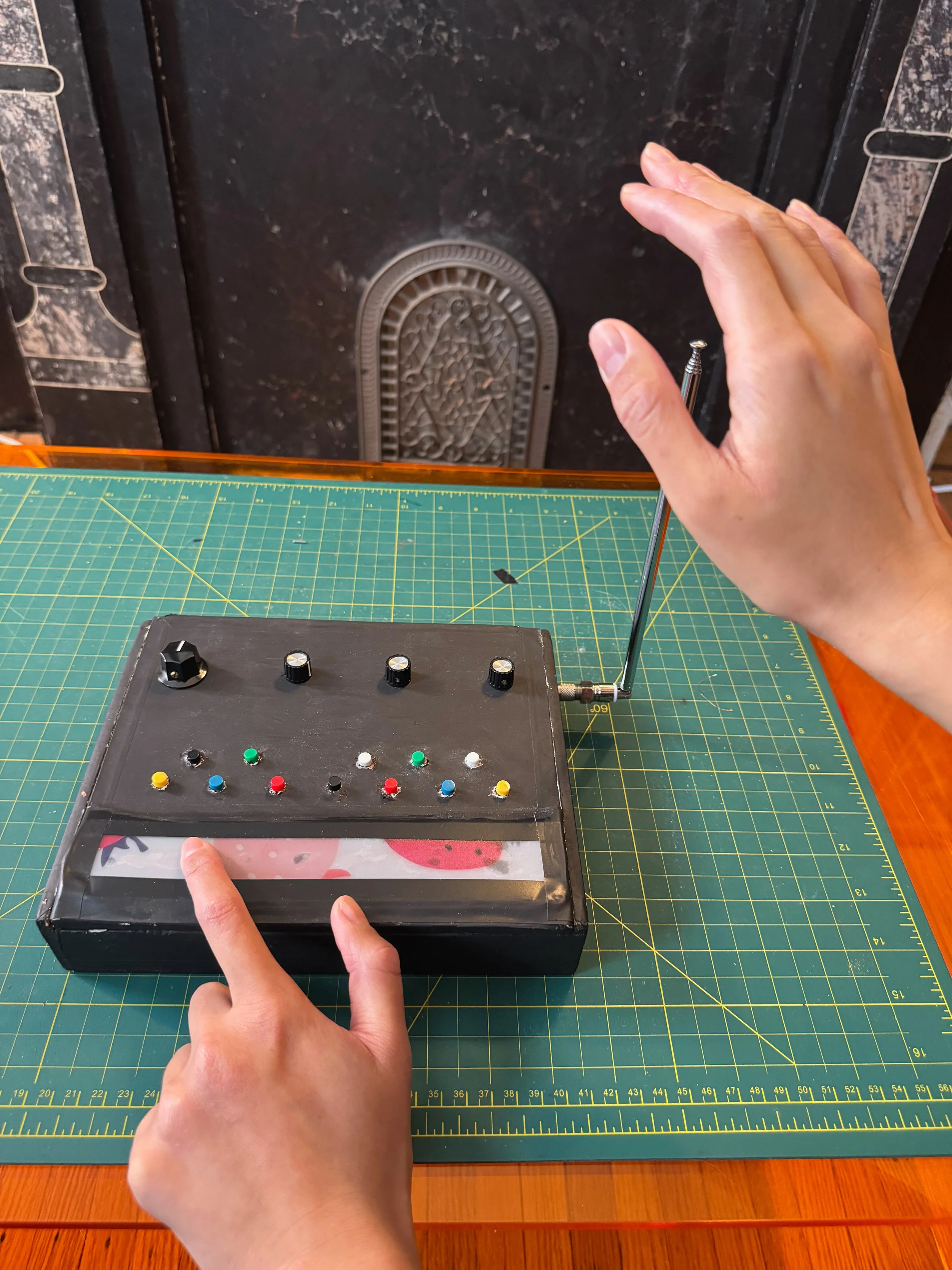
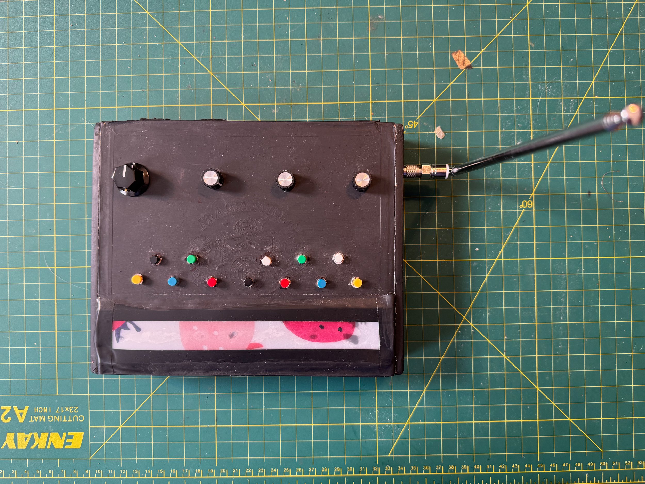
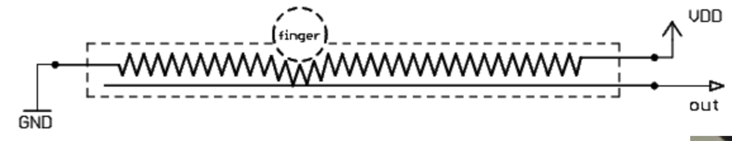
Diagram by Johannes Taelman: https://www.ooooo.be/devices/ribbon4/ribbon4.htm
Explanation of Ribbon Circuit:
When nothing is touching the tape, there is no connection between the electric circuit and the bottom copper tape, so Raspberry Pi doesn’t receive a signal. When finger touches plastic cover (4), it pushes the resistive tape down (3) so it touches the bottom copper (1), connecting the Raspberry Pi analog input to the circuit. The copper tape has much lower resistance than the tape, so the closer to 2b you touch, the less distance the signal needs to pass through the resistive tape, and the higher the voltage. Higher voltage = higher midi value.
How It Works
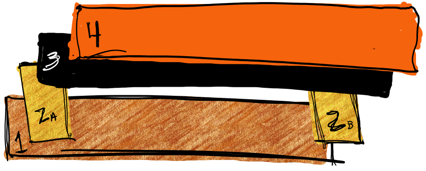
Ribbon Controller Diagram
1. Layer of copper tape connected to Raspberry Pi Analog Input
2a., 2b. 2 More small strips of copper tape (separated from 1). 2a connected to ground, 2b connected to power source
3. Layer of high resistance film, attached to 2a and 2b but NOT touching 1 unless pressed
4. Thin layer of plastic for protection
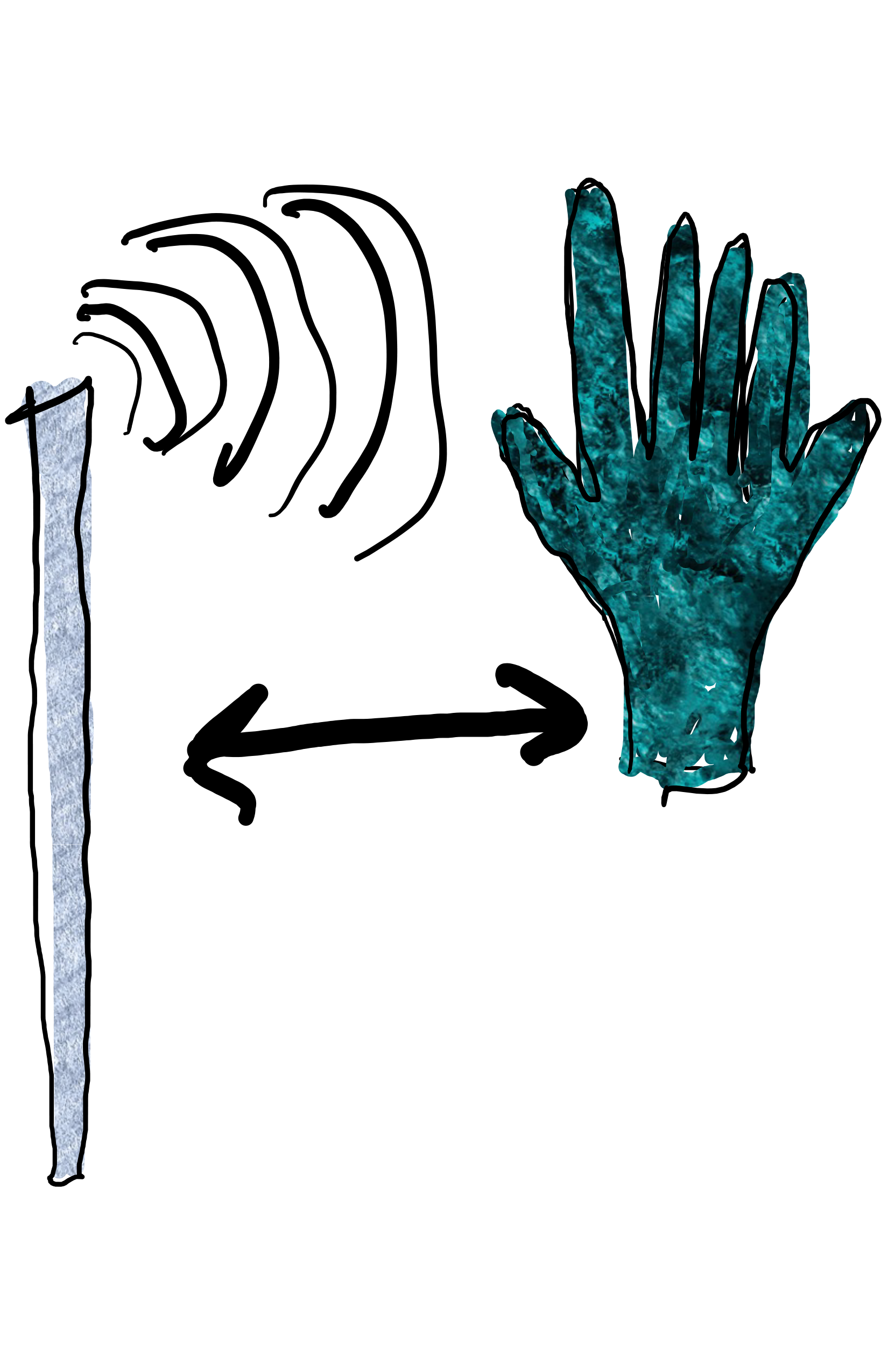
Explanation of Antenna Circuit:
Antenna acts as one plate of a capacitor, while the hand serves as another “plate.” Electric fields in body introduce additional capacitance as hand moves closer to antenna. Antenna is connected to digital input on raspberry pi which continuously charges and discharges current into the capacitor, measuring the time it takes for the signal to discharge. As hand gets closer, capacitance discharge gets slower, raspberry pi records higher value. As hand moves farther, discharge is faster, raspberry pi records low value.